You are using an out of date browser. It may not display this or other websites correctly.
You should upgrade or use an alternative browser.
You should upgrade or use an alternative browser.
DIY Spod- Waytekwire
- Thread starter pvanweelden
- Start date
CZEBJKU
New member
what size wire loom is required?
Are you following the wiring diagram? If so it shows you exactly how many wires you need for each switch.
CZEBJKU
New member
wire loom to organize the wires and protect them as well
I just went to the local auto parts store and picked up some 1/2 corrugated wire loom and run your wires through it.
x1buellist
New member
Yes, connect the negative to the negative terminal. Thats the same difference as a body ground post.
Big MAC
New member
Thanks for the inspiration guys!!!!
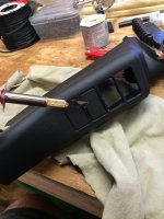
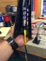
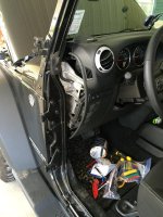
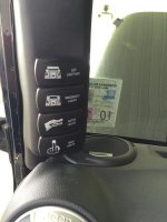
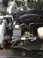
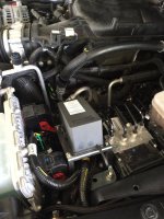
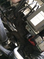
Got my DIY sPod installed in my 15 JKU Rubicon this weekend!!!!! Thanks for the write up pvanweeldn and all of the help full tips in this post.
Got my DIY sPod installed in my 15 JKU Rubicon this weekend!!!!! Thanks for the write up pvanweeldn and all of the help full tips in this post.
Attachments
-
 IMG_7366.jpg95.4 KB · Views: 363
 -
 IMG_7370.jpg85.6 KB · Views: 361
 -
 IMG_7381.jpg33.3 KB · Views: 358
 -
 IMG_7397.jpg72.5 KB · Views: 359
 -
 IMG_7422.jpg110.8 KB · Views: 366
 -
 IMG_7427.jpg75.2 KB · Views: 362
 -
 IMG_7447.jpg107.7 KB · Views: 359
 -
 IMG_7454.jpg95.3 KB · Views: 361
 -
 IMG_7455.jpg103.4 KB · Views: 356
 -
 IMG_7460.jpg91.7 KB · Views: 359
 -
 IMG_7527.jpg145 KB · Views: 362
adamsnewone
New member
Where did you get the plugs and bracket for the buss man block?
pvanweelden and all the other contributors - the detail in here is amazing. Thank you!
Quick question - if I'm planning to run 2 Rubi lockers off of this (without the harness - just doing the wiring myself), plus a hidden master "kill switch" for safety, would I (or should I) be able to use all 3 of those switches on this board? I think the locker activators are like 4 amps, so is it overkill? I would place the kill switch between the locker switch and lockers themselves, so I guess that switch would then be handling 8 amps.
Quick question - if I'm planning to run 2 Rubi lockers off of this (without the harness - just doing the wiring myself), plus a hidden master "kill switch" for safety, would I (or should I) be able to use all 3 of those switches on this board? I think the locker activators are like 4 amps, so is it overkill? I would place the kill switch between the locker switch and lockers themselves, so I guess that switch would then be handling 8 amps.
Wunderbar. Anybody mind taking a gander at my wiring diagram and seeing if it passes the smell test?

As far as I can tell, it's the same as the original, but with 2 differences to accommodate for a master locker safety switch and locker indicator on Rubi locker:
Difference 1 - My first relay will be a master locker safety switch that I'll put away from the main switch panel. Instead of the output of that relay going to an accessory, it will go to the power input on the second switch, which will be my rear locker. This way, the locker switch can only receive power when the master locker safety switch is activated.
Difference 2 - My rear locker switch will be a 2 LED switch, with upper dependent and lower independent (https://otrattw.net/CONTURA-V-REAR-LOCK ... 0-5LR.html). The power for the independent LED will be supplied by fuse 7, with the ground going to the locker indicator (not the locker actuator). When the locker engages, it closes the indicator switch on the diff, and my independent LED gets it's ground. This way, the independent LED is on when the locker is engaged, and off when it's not, regardless of if the switch is on or off.
Does anything here seem wrong? From what I've read (and again, I'm a n00b), this seems like it should work, but wanted to run it by the collective wisdom here.
lgarrett65
Member
I am curious. Can you just buy the bracket and plastic pod that mounts between the visors on the windshield? I seen where it comes with Spod.
CamBam925
New member
So I have finally got around to doing this mod and am having some trouble here at the very end. I'm not the most competent person when it comes to the electrical side of things but I do have technical skills. I figured the community could help me trouble shoot this a little faster.
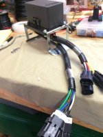
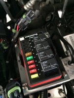
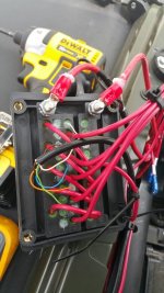
I wired everything up to the bussman following the directions of this write up, used an ethernet cable for the switches and brought power to the switches using 16 gauge wire. I have verified I'm getting power to the bussman but I'm not getting power to the switches. Do I have the bussman wired correctly? Positive and negative on the right terminals of the bussman?
During the first attempt of trying it the positive and negative terminals of the bussman were switched (too many beers while working) could I have damaged the 12v supply wire?
Attachments
Last edited:
NV375
Active Member
You do not need big wire from the switches to the relays but Ethernet (CAT5) sounds a little small. You should have a fuse for your switch power source have you checked that? Are you sure you have the same part number fuse/relay box as the write-up? There are different part numbers that look similar but are bussed different.
Last edited:
NV375
Active Member
So I have finally got around to doing this mod and am having some trouble here at the very end. I'm not the most competent person when it comes to the electrical side of things but I do have technical skills. I figured the community could help me trouble shoot this a little faster.
I wired everything up to the bussman following the directions of this write up, used an ethernet cable for the switches and brought power to the switches using 16 gauge wire. I have verified I'm getting power to the bussman but I'm not getting power to the switches. Do I have the bussman wired correctly? Positive and negative on the right terminals of the bussman?
During the first attempt of trying it the positive and negative terminals of the bussman were switched (too many beers while working) could I have damaged the 12v supply wire?
The best I can tell from the photo you wired it the same as the OP. Check fuse 6 in the new box.
CamBam925
New member
The best I can tell from the photo you wired it the same as the OP. Check fuse 6 in the new box.
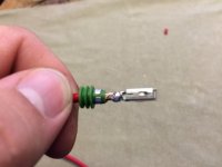
Thanks, found the problem last night. Solder and crimp came undone when pressing in the terminal to the fuse box. Everything's working now tome to install the rock lights! I did find out you can pop the face plate off with a small screw driver and unclip the terminals from that side without a special tool.
Also I pulled the data sheet for the relays and found the driving current and verified the 26 gauge wire will be fine. (If I remember correctly it was something like 100miliamps for the relay and 26 gauge wire can take up to 300miliamps)
CZEBJKU
New member
I don't know where you are intending to mount the relay/fuse panel but one other thing you need to take into consideration is that cat5 only has a temperature rating of 150 degrees. The temperature in the engine compartment will get well above that in the summer time. The jacket on the cat5 will melt and eventually short out and potentially starting a fire. Again, I would not recommend using cat5 wire in an automotive wiring application.
Bmoore0429
New member
Parts ordered. ::wait::
Bmoore0429
New member
Just buttoned up this project yesterday. Thanks for sharing. Loved seeing those lights coming on for the first time.