Clark Collins
New member
Axle swap done
Thanks to all the folks who posted info on their Rubicon axle swap and locker wiring on the forum. I kept going back and forth from my garage and the computer while doing my swap to look up various items related to it. I don’t know how I could have done it without that info.
My swap went well, but was much more time consuming than I expected. I think I lost about 5 lbs getting up and down fetching the tools I needed. 3 more axle swaps and I’ll be about where my weight should be. It took me two 12 hr days, but I only had help for about 3 hours installing the new axles and loose fitting all the bolts for later locktiteing and torqueing by myself. I wish I had made a check-off list to ensure that everything was properly fastened and torqued. I missed a rear lower control arm bolt that I only caught when doing the locker electrical hook up as the final step. I also caught a rear spring not seated properly while I was under there. Future axle swappers – do a check-off list so you don’t have to sit and stare at the axles hoping you didn’t forget something.
Following are a few suggestions that might help future axle swappers so you don’t have to search other threads for the necessary information.
1. Disconnect the cables for the hand brake from their brackets to facilitate unhooking the cable. I had the brake rotors off for this step because I think that is necessary for slack in the cable.
2. The red tab on the rear speed sensor pushes sideways to unlock the electrical connection.
3. On the front speed sensor the connection at the axle is impossible to remove or install without bending the splash guard out of the way a bit on the old and new axle. It bends right back when you are done connecting to the new axle.
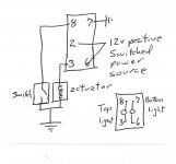
4. I suggest having the locker wiring at the axles all hooked up with the proper length of wire to reach your switches and routing that wire after the axles are in place rather than having to make those connections while under the jeep as I did. I had the wires routed ahead of time and making the final connections while under the jeep was a pain. I used one common ground from both the actuator and the indicator and one hot lead to each with different color wire. I used the Contra switches wired with the lower light wired to be hot on RUN and the upper light to be controlled by the indicator switch to show when the locker is actually on. Sort of like BADDANDY's wiring diagram.
5. The front axle takes about 1 ½ quarts of oil and the rear about 2 ½ quarts even with after-market dif covers, if the RuffStuff covers on my axles are any indication.
6. If you don’t need to lose weight, having someone just to hand you tools would be a great help. I guess a roll around tool tray could serve that function as well. A heavy duty ½” Impact wrench is not a necessity, but would probably be worth the investment for this job alone if you don’t have one. You need metric sockets from 8mm up to 22mm, a 5mm alan wrench for the front speed sensor, a torque wrench and blue Locktite . A “bull peter”, or spike if you prefer, is useful for aligning bolt holes during re-assembly.
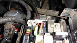
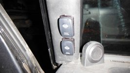
7. I used a fuse tap from the un-used front heated seat fuse position in the fuse box under the hood. I used the rear heated seat position for my LED light bar power. Both of these are only hot on RUN. (see attached photo) The existing locker fuse position is always hot or I would have used that one for the lockers.
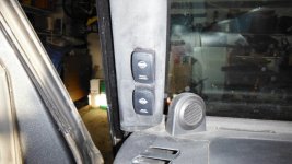
8. Other threads show a foam filled hole accessible behind the right and left dash panel end cover that provides wiring access into the engine compartment just under the rear corners of the hood. I used this access to route the wiring into the dash area and to and from the switches and the power and lockers. I cut the stock left A piller cover to mount the switches as shown in the attached photo. There is room for the switches and associated wiring to clear everything if you cut them in as close to the windshield as possible and make sure they don’t interfere with the mounting clip holes in the A piller. My photo shows the Sharpy lines, but they don't show in normal light.
9. The front drive shaft is easy, but the rear requires a drift punch to drive that connection at the axle apart. When reinstalling the rear shaft make sure you have it aligned correctly so the bolts fit through to a threaded hole and not the larger holes there for the drift punch ( I made this mistake). Tie the shaft out of the way during disassembly and you have to compress the shaft by hand in order for it to fit back into the pinion flange.
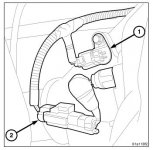
10. I got wire loom cover at Harbor Freight to protect the locker wiring. Primary wire is fairly inexpensive in various colors at any of the auto parts stores and I used 16 gauge fused at 15amps. Heat shrink butt connectors were used to connect my wires to the factory connectors that I got with my axles from another forum member.
Thanks again to all the forum members who post their “how to” threads for the benefit of us all. I hope this post is helpful as well.


Last edited:

