DIY Spod- Waytekwire

I am thinking making this and wondered if anyone makes a switch panel that fits where the power window switches are located. I have manual windows and that space is just a catch all and a perfect place to put a few switches.

I've seen somebody on the forum do this but not using this system. I'm sure it'll all work the same but try doing a search on the topic.
 
I am thinking making this and wondered if anyone makes a switch panel that fits where the power window switches are located. I have manual windows and that space is just a catch all and a perfect place to put a few switches.

The switch panel you are referring to is the one I made. I took a piece of paper and traced the outline as it sits on the dash. Then I took the rough dimensions and cut a piece of 6065 T6 aluminum and rounded the edges to fit the template. Then I took an aerosol can and rounded checking fitment as I went. Once I had the desired curve I layer out where the switches were to go. Using a multi-bit I drilled the holes to fit the switches. Sprayed it with bedliner paint. Once it dried I used 5 minute epoxy to secure it to the cubby. With the cubby I cut the back out leaving about a 1.5 inches to protect the switches. Total time to make was a solid day.

R/
Will
 

King Kork

New member
Success! Everything wired up and works great. I'll post some pictures later on but nothing you haven't seen here.

For those who put the box in the glovebox area, did you wedge it in the back left corner? I was concerned because after driving home from work and inspecting that area there are two metal pipes that run to the dash that were pretty hot to the touch. I'm guessing maybe something to do with the heater but who knows. Anyway, it seems like stuffing the box back there will have either the box or wires making contact with these pipes. Obviously I don't want to melt anything! This was a quick look so maybe I'm off base but what did you all find?

I have mine mounted there and everything is still good. Those heater core tubes would have to get really hot to melt the wires. You could put the wires in a protective cover.

R/
Will


Sent from my fRuit product using WAL
 

ljvsnyder

Member
For some reason they are not showing up on my phone. Finally got the photos to download

Sent from my SCH-I545 using WAYALIFE mobile app
 
Last edited:
What size heat shrink did you use on this project? I'll need to get some and figured I'd just order it from waytekwire. Also, for those of you that mounted the panel in the engine bay... how did you fully weatherproof the box. I know the outside has a seal, I'm more worried about the unused holes in the bottom. Will plugging it with a cable seal be enough?
 

pvanweelden

New member
I used 1/2" heat shrink over my wires going to the switches and my short relay output wires. The seals have a small hole (for the wire to go through) you could throw some silicone on the holes to totally seal them up.

Sent from my SM-N900V using WAYALIFE mobile app
 
I used 1/2" heat shrink over my wires going to the switches and my short relay output wires. The seals have a small hole (for the wire to go through) you could throw some silicone on the holes to totally seal them up.

Thanks! I'm a total newbie when it comes to anything electrical, but hopefully I'll be giving this a shot soon.
 

pvanweelden

New member
Cool, just take your time, read everything a few times :D then let me know if you have any questions :thumbup:

Sent from my SM-N900V using WAYALIFE mobile app
 
Thanks! I'm a total newbie when it comes to anything electrical, but hopefully I'll be giving this a shot soon.

So was I but this cured my fears of electrical things. The hardest part is soldiering the connectors. After the first three or four I got it down. In fact I just built up a complete wire set for another member. Took me about an hour. That is what takes the longest. If you have a riding lawnmower or four wheeler you can test it before installing it on your Jeep. Also help is available. I can assist as well.

R/
Will
 

Kavanji

Member
after reading this thread and another one about how S-Pod conduct themselves on this Forum my decision was fairly easy: I'm not going to buy a S-Pod but rather attempt to DIY something and integrate some functions that I think S-Pod forgot or never thought about.

this was the wiring mess I wanted to get rid of:

17948743sn.jpg


I still had a bunch of these Vandal proof switches so this was the switch of choice:

17948746zz.jpg


17948747ks.jpg


the mounting position of switches is a problem but after a bit of searching on the web I found someone who used this position:

17948745qw.jpg


I measured the space and decided 5 switches are enough :) :

17948748fm.jpg


17948749hi.jpg


17948750tj.jpg


I sat down and drew a diagram of what I needed and this was the result:

17948744vd.jpg


By law any driving lamps on the front of the vehicle have to be turned off when on low beam so I integrated the high beam trigger into my drawing and the capacitor / diode to overcome relay chatter caused by the Pulse width modulated headlights. I went for the 100uF capacitor because it was available at the electronics shop and it works :)
 

Kavanji

Member
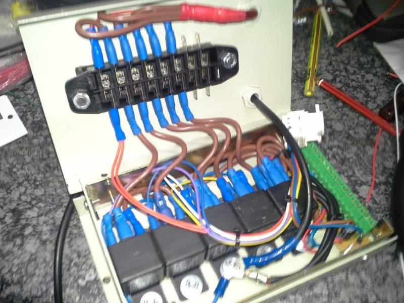
I had a suitable enclosure from a telemetry modem that I used.
here the Bosch Relays are fitted:

17949049jk.jpg


next I made a PC board for all connections and the diode / capacitor. Using resin to secure the cables at the bottom of the PCB:

17949050uc.jpg


17949051ig.jpg


whilst wiring up the relays I decided to protrude the fuse box through the lid for easy access:

17949052fz.jpg


17949053kz.jpg


17949054hk.jpg


17949055rj.jpg


Tight fit :) the CAT 5 connector is for the wiring to the dash mounted switches:

17949056lx.jpg


Fitted to the vehicle:

17949057ky.jpg


and all wired up.

17949058ym.jpg
 

Kavanji

Member
Working :

17949167ya.jpg


now I have to see if the PCB connectors are vibration proof and I still have to make a little lid so the connector part of the box is a bit more weatherproof.
 
My head is spinning right now. Looks cool but way out of my league. My hat is off to you. BTW how did you get you camera to take a backwards picture of your drivers side?:idontknow:

Looks good.

R/
Will
 

Kavanji

Member
:cheesy: we drive on the wrong side of the road. so our jeeps are right hand drive. You will notice that the battery is also on the wrong side :cheesy:
 
Top Bottom