sponnythegr8
New member
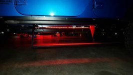
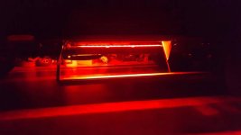
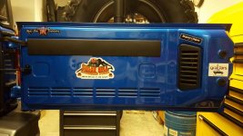
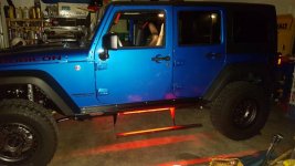
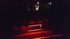
Nice job on the light. Do the Hard Rock rear bumpers have the AEV water tanks in them?
No they do not.
Nice job on the light. Do the Hard Rock rear bumpers have the AEV water tanks in them?
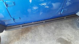
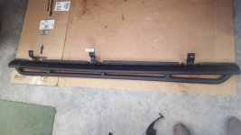
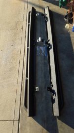

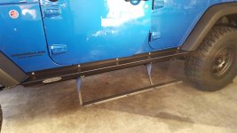
Those look really nice. I'm interested to see how they hold up.
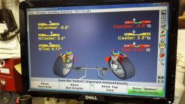
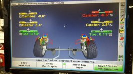
Well I finally broke down and had my rig put on the alignment rack, now I know that the only thing they can adjust is the toe in. When I took some preliminary measurements it appeared to be off and I was correct it was. But what bothers me the most is that the caster angles are down at the low end of the acceptable spec which is causing a flighty feeling in the steering. It was my understanding that the fixed LCA's that came with the Mopar stage 3 lift we're supposed to be just a little bit longer then the factory ones and should have kept me at the optimum angle of 4.2 degrees but as you can see that didn't happen. Not exactly sure what my angle was with the factory LCA'S but oh well one of those things . So now it looks like I will probably end up with some adjustable LCA'S in my future. Also my camber readings are not at their optimum location could be due to the additional weight added to the vehicle not 100% sure.
Camber on Jeep can only be affected by bent parts, worn wheel bearings or worn ball joints. Extra weight shouldn't affect it.
Yeah that's what I always thought so that means that it was probably that way from the factory. In spec but barely.
I did my lift and alignment at 9,000 miles, my camber measurements were about the same as yours if i remember right. No noticable inside edgewear on my tires at 50,000 miles
Well I guess that's all for now, we'll until my AFE y pipe arrives.
Are you doing the loop delete too or just the Y-pipe? I'm running the AFE Y-pipe, loop delete and high tuck exhaust.
Well that is good to hear, it's just a little depressing you would think that the factory would dial it in a little closer to the middle of the tolerances instead of just hitting one side or the other. Since this is the last year for the JK they are working with machinery and tooling that is ready to be replaced and they are probably just happy to see it between the lines. That was one of my concerns with buying the last year of the JK model. But then it will probably take them a few years to get the bugs worked out of the next model.