dcbjk
Caught the Bug
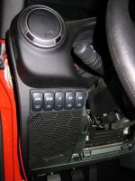
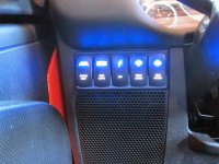
Finally put mine in today View attachment 74902 View attachment 74903 View attachment 74904
I still have put in the switches but the rugged ridge pillar switch pod came in wrong
That bracket mount used to mount the Bussman relay look good what is the Catalog number to find it on the website :thinking:
.jpg")