CJ5 Coil Over Conversion

professorkx

New member
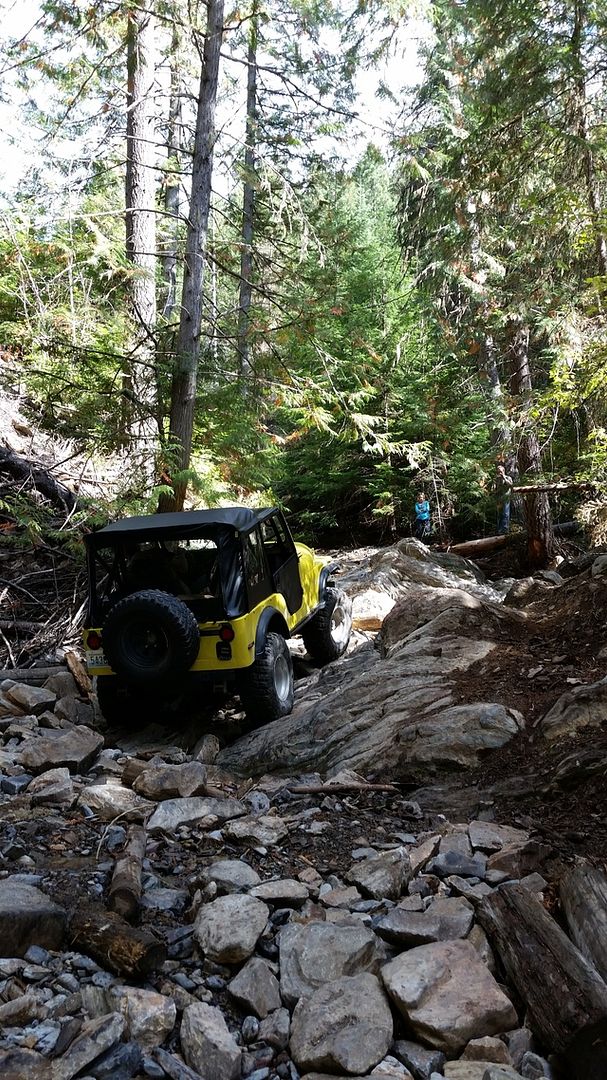
Starting a build on a 1978 CJ5. This jeep is already a great rock crawler with 304, T18 Ford 4 speed, clocked dana 20, tom woods shafts, slight lift on leaf springs, lockers front and rear and more.


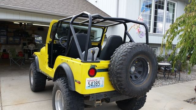
The jeep is going to my youngest son who is a disabled vet who broke his back serving our country, so needs a ride that is much better than leaf springs will ever deliver. The build plan includes changing the suspension to the a long arm using parts from Genright and King coil over shocks, moving the front axle as far forward as possible and the rear as far back as possible. The front will be a 3-link with track bar, while the rear will be a 4-link. The jeep needs to be road worthy and street legal, so we are limited on our mods.

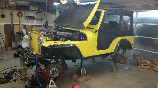
My son and I got started last weekend, put the jeep on stands, removed the 35 inch tires and pulled off the old leaf spring system.


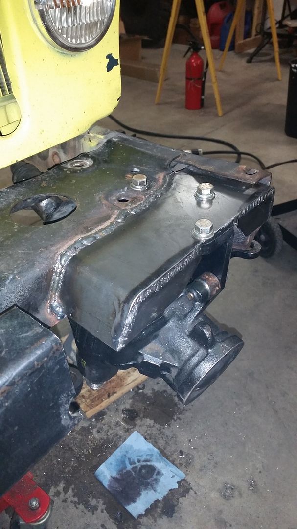
Next up was to move the steering box forward as far as possible, as this will dictate how far I can move the front axle forward. The tires can't go forward past the front bumper so he isn't hassled by LEO, but I am hoping for at least 5 inches. In the picture below, the box has been moved forward 4.5 inches, but with pitman arm modifications to yield 5.5 inches on center instead of 6.75 inches, I am going to be close.


Unfortunately, I had previously flipped the tie rod and drag link, but the frame is too low with the axle moved forward to get full travel, so they have to go back to the original spot. Might mean we have to buy new tie rod and drag link with heim joints, but hoping we can make the stock parts works to save some money.

UPS showed up with the king shocks today, so I am hoping to get the front axle arms at least spot welded in place, as well as the shock hoop. This will help determine if I need to notch the frame to allow the shocks to move on full flex.


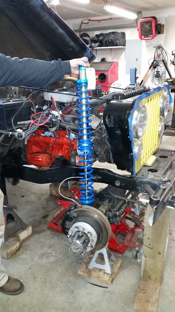
I will complete the front before moving to the rear to ensure we don't have too many things going at once. I will have to shorten the passengers side header 3 inches to have room for the top link, but stock manifolds are a backup plan. The rear frame will need to be notched for shocks, and the shocks will go into the bed of the jeep, so a new gas tank will need to be fabricated.

More pictures to come as progress continues...
 

professorkx

New member
Big progress today, with the lower control arms tack welded in place.


Picture from the front under the front axle.


From the side


from the rear.

Tomorrow will be the axle bridge up front and the third link. I am also hoping to do some work on the track bar, but need to do some research, as I have read that the axle end needs to be at the same level as the drag link at the knuckle, while the frame end needs to be at the same level as the drag link at the pitman arm. The knuckle end is going to be very difficult if it has to mount as the same level as the drag link because of the differential, so might have to bend the track bar to get clearance.

Hoping to be mounting shock hoops on Monday, but only if everything cycles OK without the shocks....
 

professorkx

New member
Today was another big day on the CJ5 coil over conversion. After finishing the trailing arms, it was time to tackle the third link on the top. Since I am using Genright brackets, I tack welded the third link frame mount in place when I installed the control arm brackets. Oh yes, forgot to note that my lower control arms are 35 1/2 inches on center, as long as possible, which should make this system work well.

The first thing to tackle this morning was the axle bridge. I had purchased a length of 2" x 3" x .250 tubing for the front axle bridge, but there was no way I was going to fit 2 inch tubing on top of my axle and still have any upward travel. So, I marked down the center of the 2 inch legs on each side and cut the tubing in half using a metal saw blade in my Makita worm drive skill saw. This gave me a 1" x 3" formed C to start with. Using a 2 3/8 hole saw in the drill press, I cut a hole forming a "C" for the contour of the axle. We slipped the "C" over the short side axle on the passenger side and market the spot for a bend. I cut straight down the leg at the mark, drilled a hole at the end of the cut, bent one leg out so it could slip over the other during bending, and using a narrow break press I built that fits on the inside of the C between the legs, I bent the steel to the appropriate angle...which took three bends to walk it into the right spot.

I repeated this step for the down angle on the other side, drilled another 2 3/8" hole and cut off the excess. I also drilled a hole in line with the breather, and will install a nipple after everything is welded in place. Finally, I cut 1/4" x 1 1/2" flat bar to length and welded on the underside of my Bridge to add strength. no one will ever see this bar, but at 1/2" thick, this Bridge won't bend once welded in place. I will add a bolt on plate that wraps around and bolts to the top differential cover bolts later. Here is the finished product.


I left the legs on each side around the axle long, as these will be trimmed to mate to the track bar axle mount and welded together when all is finished. The distance between my Johnny Joints is 9 1/2", so should be plenty to hold things in place. Oh yes, I installed an insert on the knuckle so I could flip the drag link and run it on top. This not only gives me a flat drag link that is parallel with the tie rod, it move the axle mounting point for the track bar above the tie rod. This may not seem like a big deal, but space is very limited on the CJ5, so flipping the drag link means my track bar can be mounted above my tie rod with more than 3 inches of clearance and the track bar doesn't need to be bent to clear the differential. Essentially, my track bar sits directly behind my drag link on the exact same plane as my drag link, just offset to the drivers side and the exact same length as my drag link.

Next up was testing droop and cycle for articulation. All I have is a couple of jacks, but they worked to get a 2 foot side-to-side difference on articulation.


This is a picture of the droop test. None of the brackets broke the tack welds, so no binding, but I didn't really expect any issue on the droop test. I am not going to be able to use all of the 14 inches of travel in the shocks unless I build a new motor mount bracket on the passenger side and use an oil filter relocation plate to clear the third link as is gets to the top of the stroke. I won't deal with that now, as 12 inches of travel will be fine to start with, but it's nice to know the additional 2 inches is there if I want it.


Here is the high side on the first articulation test. Remember, I only have 4 small tack welds on each mount, as I want them to break the tack welds if they bind. Better to deal with it now instead of after something breaks from being in a constant bind.


This is the low side on the first articulation test. Notice the difference in the brake lines in the high side and low side. 2 foot side-to-side difference should do the trick in any rocks. I am going to use a long travel slip yoke when I have the new drive lines built so my son can use all of the articulation.

I started the track bar today, and quite frankly, getting the track bar in the right orientation to the drag link was a ton of work. i have already built the frame mount and tack welded it in place, but my creative juices were gone by 7 pm, so thought it best to table the axle mount until tomorrow mourning. I am hoping to have the track bar installed so I can cycle the suspension to test for binding tomorrow morning, then tackle the shock hoops and cross over bar. If all goes well, I should have everything tacked in place by end of day tomorrow and can finish weld everything during the week after work. Once the front suspension is done, I still need to shorten the passenger side header 3 inches by cutting each of the 4 down tubes, flaring each tube and fitting the tubes back together for welding. The collector needs to come up 3 inches to clear the frame mount for the third link, then I have to modify the 3 inch exhaust to match to the new collector location.

Might be starting the rear 4 link suspension in about 2 weeks, but i will post a task list when I start the rear for those who want to follow the build. My youngest son is helping me on this build. This jeep is for him, and he has a great fabrication mind as well, so we are having a blast designing and fabricating everything. Quite frankly, I wouldn't want to be doing this with anyone else...

More pictures tomorrow...
 
Last edited:

professorkx

New member
Today was the 5th day of work on the CJ5 coil over conversion project, and we have SHOCKS!!


Here is the drivers side shock on the hoop (we still need to relocate the brake lines, but I want everything installed first). We have the springs removed as all brackets are just tack welded in place, so won't take the pressure exerted by the springs. We still need to add the bottom shock mount gussets and shock hoop engine cross over and then we will cycle everything for the 5th time. We have cycled the suspension up/down and side-to-side articulation at every step to make sure everything is working as designed.


Here is the Passengers side shock mount.

The biggest problem so far was the track bar. Last night when we quit work, we thought we had the track bar mount figured out, but we didn't realize the jack had lost a little pressure and the axle was no longer at full stuff. When we jacked the axle to full stuff, the track bar made contact with the tie rod when we turned the steering to full lock...back to the drawing board.

After 5-6 hours of trying to find a suitable mounting spot, my son suggested mounting the track bar behind the axle. Well, I said that just wouldn't work and would result in interference. He persisted (did I already say he has a great fabrication mind?), and since nothing had worked all day, we welded up a couple of mounts to test his suggestion to mount it behind the axle.


What do you know, it worked. We had to give up a little travel, but we can live with that since the track bar worked so well as we went through all the cycles. I doubt this would work on a Dana 44, but on a narrow track Dana 30 with a small pumpkin, there was just enough room for track bar to clear the third link and the top of the differential with 1/2" to spare on both top and bottom during articulation testing. (oh yes, the angle iron welded to the frame above the axle is to simulate the bump stops so we get accurate cycle testing)


Here is a picture from the front at full droop. Notice that the track bar and the drag link are almost perfectly aligned, so should have the exact same arc...which means no bump steer.

I still need to tack weld gussets on the bottom shock mount, build bump stops and put a 2x4 between the shock hoops for support to simulate the engine cross over during cycle testing (I don't want to install the cross over until the final cycle text in case the test shows I need to change a mounting location of the shock hoops).

I have to work my real job until the weekend, but I think we can be done with final welding of the front suspension by the end of next weekend! Progress, progress, progress...
 

professorkx

New member
This weekend was spent finish welding brackets to the frame, shock hoops and brackets on the axle. However, since axle welding is a slow process, I decided to tackle the header modification that was necessary to clear the passenger side suspension frame brackets. I've never tried anything like this before, but a friend has a set of stock manifolds if I was not able to modify, so there really wasn't any risk.


This is the header in original configuration. You can see that the collector is behind the frame rail and runs along the inside of the frame. However, that's right where the third link and lower control arm mounts to the frame, so I decided to attempt to shorten all four header tubes to move the collector above the frame. With the slope of the floor, I have enough room for the exhaust collector to bolt to the header and route beside the Dana 20 Transfer case.


First thing to do was to cut the header tubes so I could experiment with different modifications, as I needed to pull 4 inches from the down tubes to clear the frame brackets. The header tube on the back cylinder proved to be the most problematic.


After 5 hours of work (with intermittent welding on the axle brackets), here is the new header. As you can see, the header now rides above the frame rail and exits above the third link bracket. Just some clean up and ceramic paint and the new header is ready to install.

Everything should be all cleaned and painted by next weekend so we can do final assembly and maybe even a test drive before we start the rear 4 link.
 

professorkx

New member
Front suspension is finished and installed, so thought I would share a few pictures. We bolted the fenders in place to test fit our inner fender cuts, but I still have to install the bump stops and limit straps once the parts arrive.


We built a truss on the long side of the axle to add strength. This rig is a daily driver and periodic 4x4 trips, so needs to be road worthy. We got more lift that we wanted, but once the front winch/bumper is installed and we take it for a drive, I think it will settle 1-2 inches. If not, I will start to play with spring rates to get the ride height and ride quality we need. We still haven't decided if we want to use the 35" or the 33" tires. I have full sets of each in KM2 and both sets are new, but won't decide until we drive it.

We disassembled the rear suspension, exhaust and drained the gas tank last night, so the conversion continues. The front axle is moved forward 4 inches, and the rear will be moved back 6 inches, for a total 10 inch stretch.
 

RageKage

Member
That is a thing of beauty! I have a '74 CJ5 and really want to do a leaf over conversion. If I had the skills and knowledge as you this would definitely be the way to go! Looks amazing! Can't wait to see the finished product. Give your soon a huge thanks from a fellow service member!
 

professorkx

New member
I did my first spring over axle in 1980, and everyone told me at the time that I was nuts...now there are kits all over the place, so spring over axle is a pretty straight forward conversion. More difficult on a YJ, as you can get bump steer, so I've installed high steer to solve that problem for others, but never had a problem with a CJ spring over.

This is my first attempt at a linkage suspension on a CJ (3 link front and 4 link rear). If I can find a solid CJ during the spring/summer with a v-8 drivetrain, I will build another one just for fun over the winter and then sell it during the following spring/summer. Will give me something to do when the snow is on the ground.

My oldest son has a 2007 JK, and he's been talking about a V-8 conversion, so I expect I also have that in the future as well. We will change motor/transmission/transfer case, so that conversion will be pretty easy...

Have fun with your CJ5. It's my favorite jeep model, but my 2014 Rubicon X is just more comfortable to drive to 4x4 destination than a CJ...
 

RageKage

Member
Have fun with your CJ5. It's my favorite jeep model, but my 2014 Rubicon X is just more comfortable to drive to 4x4 destination than a CJ...

I love my CJ I just didn't bring it to Alaska with me because it needs too much work. I plan to do a frame off resto in the future and have it be my daughters first vehicle. She is my oldest and only 3 so I have plenty of time as I want her to build it with me. But as you said my 2014 JKU sport is just way more comfortable and fits the whole family.
 

2Cross

Caught the Bug
What an awesome thread.
Nice fab work. My first jeep was a CJ5.
Yellow just like yours [emoji106]
 

professorkx

New member
Used some vacation time and spent 4 days working on getting the rear 4 link suspension finished. Quite frankly, the rear was a ton easier than the front, as we didn't have to deal with steering, headers, radiator hose and everything else thats sitting under the front of the jeep. As a result, the rear went pretty smooth

This first picture is of the suspension mocked up and at full stuff. You will notice that the frame has been cut, as the rear shock towers had to be recessed 6 inches from the outside of the frame, so a new rear frame, which wasn't originally anticipated, was added to the To Do list. The shock towers were also recessed into the bed of the jeep, which means our new rear seat will only have room for one adult when I am finished. The front of the wheel well looks like it has been cut too high, but that's just old paint from a previous owner who couldn't be bothered to remove the fender flares before painting. The radius at the front and rear of the opening is the same as we used the original fender flares as our guide. New custom metal flares were always on the list...


This is a 2 photo set showing the rear axle truss in mocked up form and the finished product. The gussets are 3/16 steel, so the truss isn't going anywhere.


The two lower link mounts still need paint, as I ran out of mig wire, so had to finish the last 4 welds the next morning. I've used aver 10 pounds of wire welding everything in place, and most of the welding has been done flat on my back.

Pictures after everything was mounted. The jeeps is 3 inches too high, so working with King to get the right springs in place. Since this is a street rig, my son doesn't want it so high.


You can see the new rear frame piece in the second photo, and it's 2.5 x 3.5 x .250 tubing, so a lot stronger than the original 1/8" C channel. The frame pieces are 2x3x.250 tubing and tie back into the original frame on the inside 24 inches from the rear of the jeep. I will also be adding a 2x3x.250 tubing cross member at the end of the new frame pieces to add strength.

Still a lot to do while we wait on new spring from King, and I think the exhaust routing is going to be the most challenging...next weekend....
 

professorkx

New member
This series of photos is probably more detail than most folks are interested in seeing, but I thought I would post for others who are doing a complicated project like this of their own.

There are always a lot of little things to deal with on a project of this size, but there are also those sub projects that are complicated and take a lot of noodling to come up with an acceptable plan. On this CJ5 build, building a gas tank was one of those complicated projects that took a lot of planning. I wanted to use a fuel cell, but my son wants to be able to have some kind of rear seat, but also wanted a minimum of 20 gallons so he wasn't constantly stopping for fuel. The 10 inch stretch chopper I built several years ago has a coffin style tank that only holds 1.6 gallons, and while it looks cool, I have to fill up the tank every day I ride the chopper to work, so I understand his desire for a larger tank. Since I moved the rear axle back 6 inches, using the original gas tank was not an option, which meant building a custom tank.

The first step was to get a rough idea where the tank COULD fit, then drawing the tank on graph paper. To get 20 gallons, the tank was going to have to go through the floor, but maintain a shape that would allow for a back seat. After taking a lot of measurements, here is the drawing for the shell.


I knew I would have to deal with differential clearance, but decided to mock the tank up, put it place and then measure for differential clearance.


Using 1/8" steel plate, I cut to the overall dimensions and marked all of the lines for bending. I have built gas tanks in the past by cutting each sheet individually and welding them together, but those tanks were rectangles with a 45 degree bottom corner for departure angles. Bending this tank into shape seemed the best option, as I would only have 2 seams and the angles would be easier to maintain with bending than welding.


I don't have a fancy brake press, but I do have a 19 3/4" brake press I built last year that would work. The tank is 21 inches wide, so in order to fit into my brake press, I used a hole saw to cut half circles at each bend line. I would have to fill these half circles during final welding, but that won't be a problem.


Because I had drawn my tank profile to scale, I was able to determine angles and the distance between bends on those angles. A $5 angle gauge from harbor Freight did the trick to bend to the correct angle, which was important since I only got one chance with each bend.


Because of clearance issues, I started with the bends in the middle then worked my way to each end. This was another reason I only got one shot at each bend, as I wouldn't have the clearance to go backwards.


Here is the bottom/back of the tank shell. I wish I had a spool gun or Tig, as I would have made this out of aluminum, but since I only have a Mig welder, the tank will be heavy, about 50 or so pounds, but not heavy enough to be a big problem.


With both shell pieces bent according to my drawings, I spot welded the two together for a test fit and to measure for differential clearance. After measuring, I cut the spot welds to separate the two sections and made 3 more bends to arrive at my final shell shape.


These pictures show the finish welded shell with the half circles filled in with small plates bent to math each angle. On the 45 degree bottom angle, I will bent the original half circle cuts, weld them back into place and finish for aesthetics. The final steps are to cut out the two sides, weld them in place, weld two tubes at the top for the filler and the vent, add a bung on the drivers side bottom for fuel pickup, pressure test and modify the stock sending unit. Only the large bottom section will be read by the sending unit, so the top 3.5 gallons will be used before the needle comes off full.

This is a lot more work than most folks would put into a gas tank, but given my son's criteria, there really wasn't any other choice but to tackle this polygon...the things we do for our kids...
 

professorkx

New member
The kit was made for a TJ, so had to be heavily modified for the CJ. For example, I put the track bar behind the front axle, which required heavy modifications to the original brackets in the kit. However, the kit was very complete. The instructions were also very complete for a TJ, and I think the installation on a TJ would have taken a lot less time.

There were so many changes required and custom brackets required for the CJ, not sure I would use the kit again on a CJ5. However, Since this was my first coil over conversion, the instructions helped a ton, but now that I understand the concept, all I need are the key link brackets, as they would be a pain the build.

If this is your first conversion, use a kit with good health instructions.
 
Top Bottom