SwankPOD (DIY sPOD) write-up (My last name is Swank)

Rebel JK

New member
J- thanks again for sending the diagrams over. It is really well done and easy to follow. One question I have though is where did you terminate TB1- 11 and 12 on the other end for the locker bypass, are you just paralleling the factory connection at the lockers? I think you mentioned above that your factory switch will stiil work. If so how did you physically tie this in?
 

KPM171

New member
I didn't. All the holes are on the bottom of the box and so anything that comes in should drain out. The lid overhangs all the sides to help keep stuff out. In the end this box it higher than my air intake. If it gets wet I have other issues.

If you're a deep water/mud guy you might need to add some provisions. I am not so it wasn't a concern.

To the best of my knowledge the sPOD isn't sealed either but I don't know for sure. I've never seen one in person.

You are correct, the sPOD isn't any more sealed than your box is. Fantastic work by the way.
 
J- thanks again for sending the diagrams over. It is really well done and easy to follow. One question I have though is where did you terminate TB1- 11 and 12 on the other end for the locker bypass, are you just paralleling the factory connection at the lockers? I think you mentioned above that your factory switch will stiil work. If so how did you physically tie this in?


No Problem, glad to help... and sorry for the delayed response. I have been putting my EVO D-Ring mounts in. My bumperless rear is complete :rock:

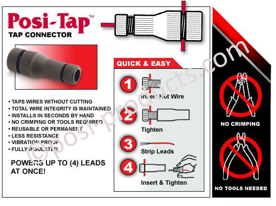
I hate to send you to a link on another forum, but I did some searches here and didn't see where it was documented. Here is a link to a write-up on JKF -> http://www.jk-forum.com/jk-write-ups-39/rubicon-owners-locker-modification-88085/ I think it will answer your question on where to tap in to the stock harness. One thing of note is that I don't like the splice connectors that were used I prefer these:
posi-tap_n2_a2-b.jpg

Obviously you can ignore the rest of the wiring in the write-up as it is covered on my diagram. Essentially you are providing the ground side to the coil of factory relay that engages the lockers. The hot is always there when the engine is running.

Hope this helps, let me know If you need anything else!
 

Rebel JK

New member
Just got thru the link. Is pretty simple as you are just tieing in at the easily located relay and running a seperate ground path thru a switch.
How about for the guys swapping out there non locker axles to rubi e lockers? just add a couple of new relays and wire the same right? The main difference is the wiring of course will need to be routed down to the lockers.

I would think so but 'm not certain. I would think you are energizing the solenoid for the locker in the same manner as any other aux electrical device... i.e. lights or compressor. If the Jeep wasn't originally equipped with lockers I wouldn't worry about the bypass feature and trying to gain factory operation. I would just plan on using them with the switch you add.

Note: In my SwankPOD I switch the GND because this is what is needed for the Rubi locker bypass. It is more common to switch the positive, then you can just grab a good ground at the frame or some place close.

I hope this makes since... I'm not through my morning Monster yet :crazyeyes:
 

Lagavulin

New member
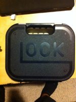
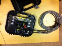
Finished mine a couple weeks ago but forgot to Aka was too lazy to post pics. ImageUploadedByWAYALIFE1382594329.027448.jpg ImageUploadedByWAYALIFE1382594361.101254.jpg ImageUploadedByWAYALIFE1382594405.016061.jpg
It took me weeks to fabricate it working little by little on it each day. Originally I had it made up inside a playstation2 box but switched to a glock case. I made the switch pod out of a piece of the playstation2 box and pieces of an erector set. In the picture the 9 wire cable is running down the windshield but I changed that to run down across the top and down the inside of the pillar. I also only have one led switch installed due to only having windshield lights installed and a budget. With the addition of more equipment I'll add the other switches. Swank was a big help during this project as I found myself stuck multiple times and through email he helped me tremendously.
 

Charmander

New member
What kind of connector hooks to the back or ur switches. Looks like it was made for it obviously? Have a link for that?


Sent from my iPhone using Tapatalk
 
What kind of connector hooks to the back or ur switches. Looks like it was made for it obviously? Have a link for that?


Sent from my iPhone using Tapatalk

The switches have solder terminals. I soldered the flying leads of a cable that is regularly used in the automation world. It has a connector on the other end that mates to a receptacle at the box. If I were to build another I would just use a standard multi-conductor cable and skip the connector and receptacle. The relays just use a crimp on spade connector. The full bill of material is in my post.

Hope this helps.

sent from my wiz-bang time killing machine
 

gtony12

Caught the Bug
Nice job looks great. :thumbup: Did you use a devicenet cable?

Sent from my SCH-I545 using WAYALIFE mobile app
 
Nice job looks great. :thumbup: Did you use a devicenet cable?

No that is just a Turck multi conductor cable with an M12.

I work with Siemens automation and drive products to devicenet is one of the many tools of the devil ;)

I spend more time working with Profibus or Profinet than anything, but Siemens did just make all their drives Ethernet IP compatible so I will be dealing with the AB guys more :crazyeyes:
 

gtony12

Caught the Bug
No that is just a Turck multi conductor cable with an M12.

I work with Siemens automation and drive products to devicenet is one of the many tools of the devil ;)

I spend more time working with Profibus or Profinet than anything, but Siemens did just make all their drives Ethernet IP compatible so I will be dealing with the AB guys more :crazyeyes:

Yes, very cool worked on jobs with Siemens and used many products on jobs too here in California.:thumb:
 

Ddays

Hooked
Just came across your SwankPOD doing some research on the SPOD & Painless systems. Wow - that system is a work of art, man. I'm jealous and wish I had your electrical acumen & fabrication skills!

I was originally going to PM you saying this but then I thought I'd bump this up so others could enjoy seeing the system you fabbed up since this thread is a few years old! :2thumbsup:

Thank you for the complement. As you mentioned, this was done a few years ago and when SPOD was the only option. If I were diving into this now I would definitely go the route of making my own switch box but the power distribution would be Painless Wiring. The only reason I would make my own switch box is I have a manual transmission and I don'y like their switch location. (I also have a Rockhard cage so the a-pillar is out.)
 
Thank you for the complement. As you mentioned, this was done a few years ago and when SPOD was the only option. If I were diving into this now I would definitely go the route of making my own switch box but the power distribution would be Painless Wiring. The only reason I would make my own switch box is I have a manual transmission and I don'y like their switch location. (I also have a Rockhard cage so the a-pillar is out.)

Your setup looks awesome, it's always cool to see great custom setups like this. :thumb:

We actually just realized our kit sans switch panel for those that want to run their own switches. Along with that, we are working on an a-pillar mount, but just got our switch boxes in that mount above the mirror very similar to your setup.

Obviously not needed for you, but a heads up to others following. :)
 
Top Bottom