You are using an out of date browser. It may not display this or other websites correctly.
You should upgrade or use an alternative browser.
You should upgrade or use an alternative browser.
The Uncharted build
- Thread starter IceKnight
- Start date
IceKnight
New member
this is epic!!! You have skills bro:rock:
Thanks, it's been one heck of a learning experience.
IceKnight
New member
So, staples removed, healed up enough and Amsoil convention in the rear view mirror. I had just 2 weeks of work before a trip with my wife to Vegas (her first time, I have been a few times for SEMA) we had plans for the normal Vegas stuff, but the main reason was hiking the local national parks. Then on Aug 2nd, all of that came an explosive halt. At work a split rim truck tire blew up in my face, shooting me across the garage leaving me with an egg on my chin, jaw 3/4" out of whack and a broken left arm. I got out of that one lucky considering I called 911 myself and I'm still breathing and functioning properly now. Oh yeah, not wanting to mess up my wife's only vacation for the year we still went.
How about some broken arm x-ray pics. This was after a month of healing.


How about some broken arm x-ray pics. This was after a month of healing.
pvanweelden
New member
Man, you are as unlucky as I am  Glad you were ok :thumb:
Glad you were ok :thumb:IceKnight
New member
So, to say that pushed things back a bit would be a little understatement. So much for my Sept first drive wish. Pains and hand spasms made my left hand mostly unusable. But hey no biggie, moved on and made good head way with a little help from family and working extra slow with one arm/hand I was able to make slow progress.
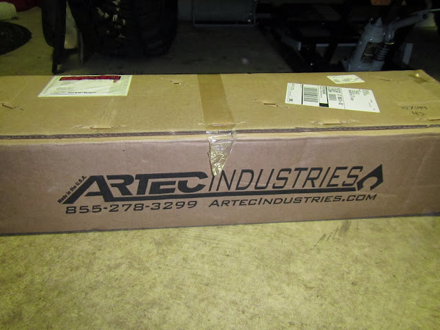
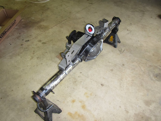
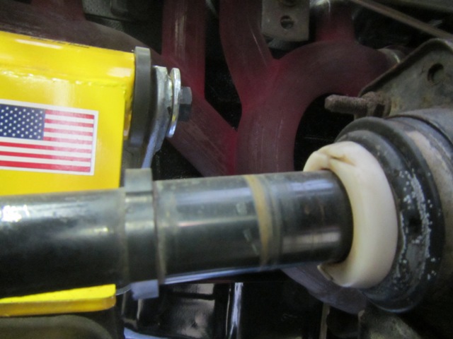
You have seen my rear axle already, but as mentioned before I welded everything on at the wrong angle. Running an sye, I had to have a much steeper pinion angle for everything to work correctly. So I cut off all the brackets and ordered up an Artec truss.
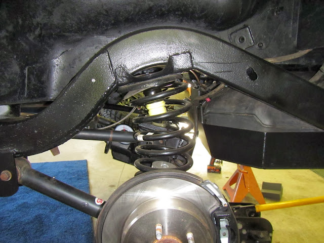
I also came across someone who had a Rokmen rear spring perch leveling kit, so I picked that up as well. Here is a before.
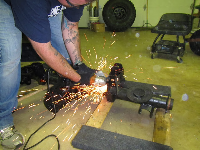
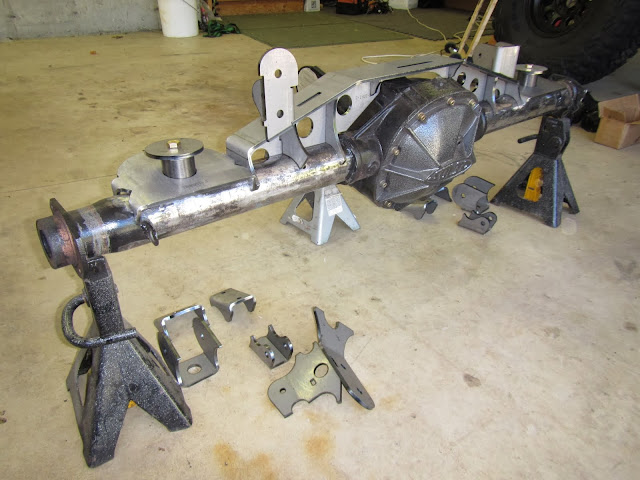
My brother came down to help out with the bracket removal and tube clean up. We set everything on the axle to get a feel for what we had to work with. Very well designed kits.
Before welding anything in place used a bandsaw to cut the two tabs down for better sway bar clearance.

Set the pinion angle and made sure the truss was set at zero (compensating for the slight angle (1 deg) of the garage floor) and tacked everything in place.
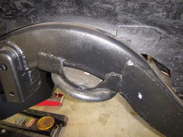
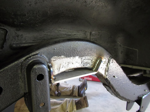
Moving back to the frame and the upper spring mounts we cut off the old mounts, cleaned and welded in the new mounts.
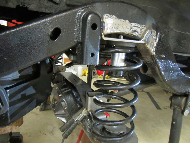
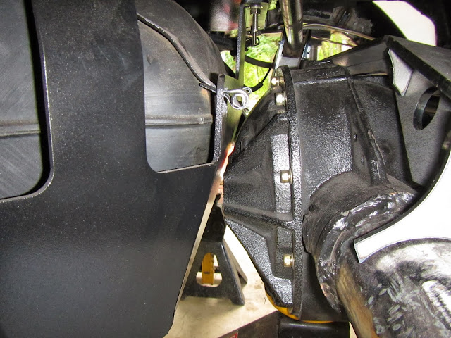
We then slid the axle under the Jeep and checked for clearances, things fit...just
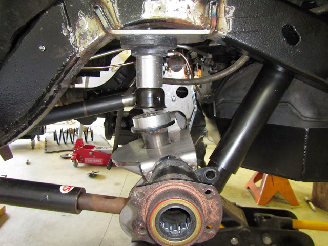
After that was fitted I moved onto the 8.8 axle shaft install to eliminate the c-clips and add strength
Cutting the bearing end off is the first thing to do leaving the shoulder


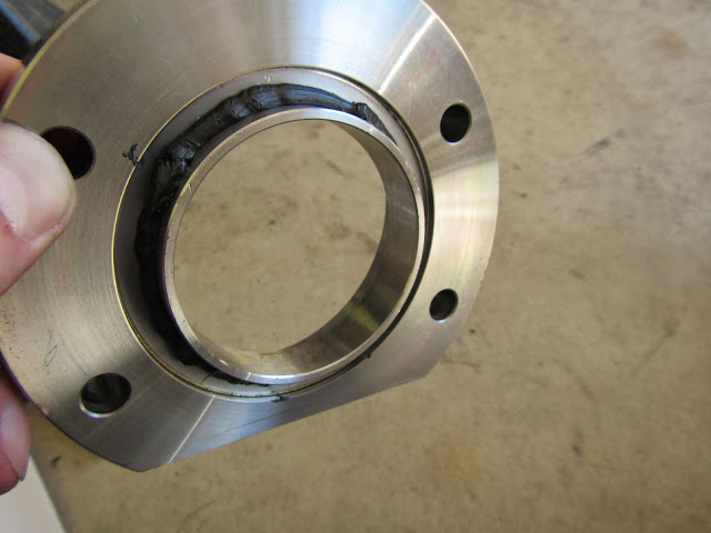
Great Stuff RTV on the new housing end
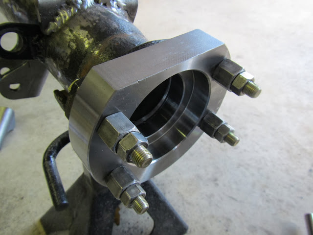

All the bearings lined up and ready to be pressed on
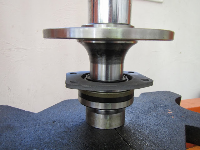
And here is almost of everything welded on and setup
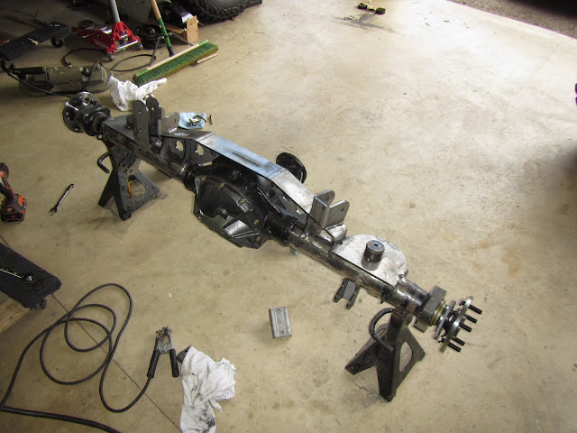
After that came a coat of paint and under the Jeep it went.
You have seen my rear axle already, but as mentioned before I welded everything on at the wrong angle. Running an sye, I had to have a much steeper pinion angle for everything to work correctly. So I cut off all the brackets and ordered up an Artec truss.
I also came across someone who had a Rokmen rear spring perch leveling kit, so I picked that up as well. Here is a before.
My brother came down to help out with the bracket removal and tube clean up. We set everything on the axle to get a feel for what we had to work with. Very well designed kits.
Before welding anything in place used a bandsaw to cut the two tabs down for better sway bar clearance.
Set the pinion angle and made sure the truss was set at zero (compensating for the slight angle (1 deg) of the garage floor) and tacked everything in place.
Moving back to the frame and the upper spring mounts we cut off the old mounts, cleaned and welded in the new mounts.
We then slid the axle under the Jeep and checked for clearances, things fit...just
After that was fitted I moved onto the 8.8 axle shaft install to eliminate the c-clips and add strength
Cutting the bearing end off is the first thing to do leaving the shoulder
Great Stuff RTV on the new housing end
All the bearings lined up and ready to be pressed on
And here is almost of everything welded on and setup
After that came a coat of paint and under the Jeep it went.
IceKnight
New member
Man, you are as unlucky as I am
Dare I ask what has happened to you?
pvanweelden
New member
Lol, well most recently was caught a metal fragment in my eye, had to get it drilled out
pvanweelden
New member
no, I got some drops in my eye, and then he went to work with the drill. It wasn't much fun, there's a pic of it in my build thread.
my fault for not remembering to put the glasses back on :doh:
my fault for not remembering to put the glasses back on :doh:
IceKnight
New member
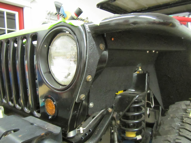
After I got the axle installed I moved onto the front indicator lights.
I have a 2.5" LED flasher in the grille and a .25'' LED marker under the fender.
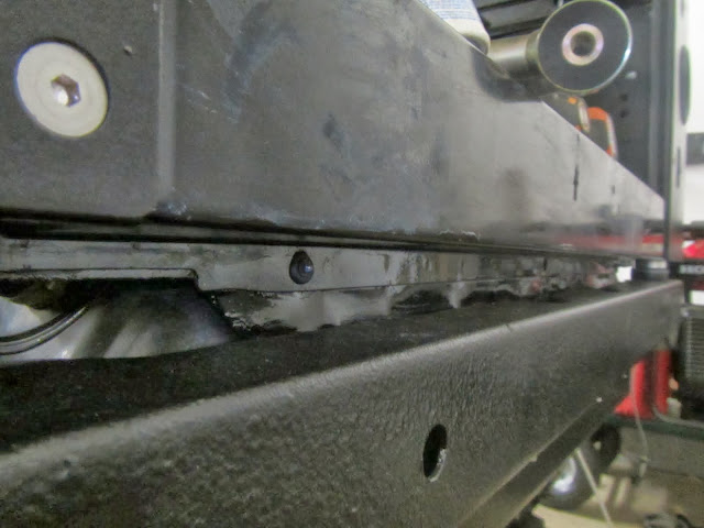
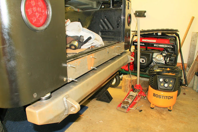
I also installed some hidden reverse lights in the tub just above the rear bumper and below the tailgate.
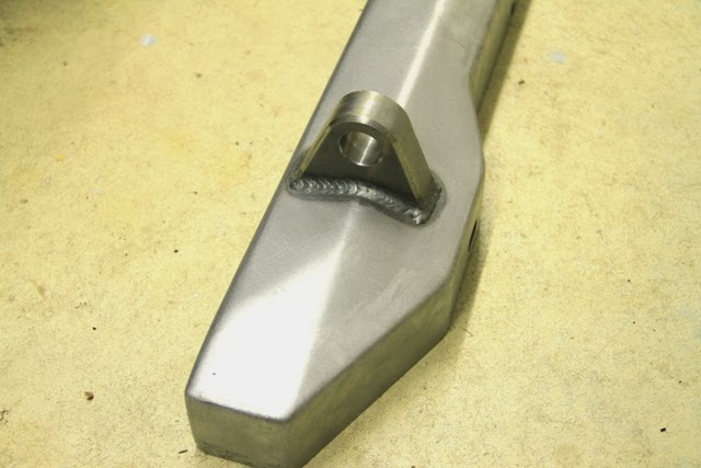
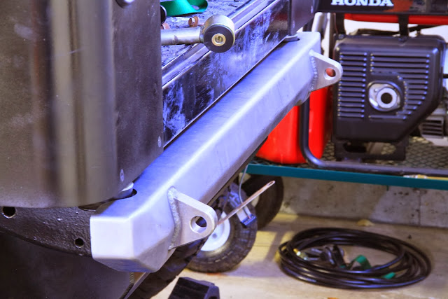
Speaking of rear bump this is around the same time it showed up from Northridge4x4. It's a Poison Spyder BFH-2

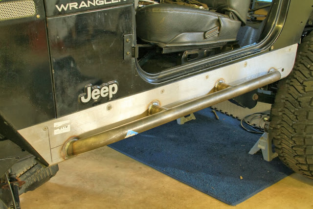
And my Rokmen rocker guards
I have a 2.5" LED flasher in the grille and a .25'' LED marker under the fender.
I also installed some hidden reverse lights in the tub just above the rear bumper and below the tailgate.
Speaking of rear bump this is around the same time it showed up from Northridge4x4. It's a Poison Spyder BFH-2
And my Rokmen rocker guards
IceKnight
New member
So after building my Ford 8.8 twice and installing it in my Jeep I realized I never installed new clutch packs for the LSD.
So here is a little write-up.
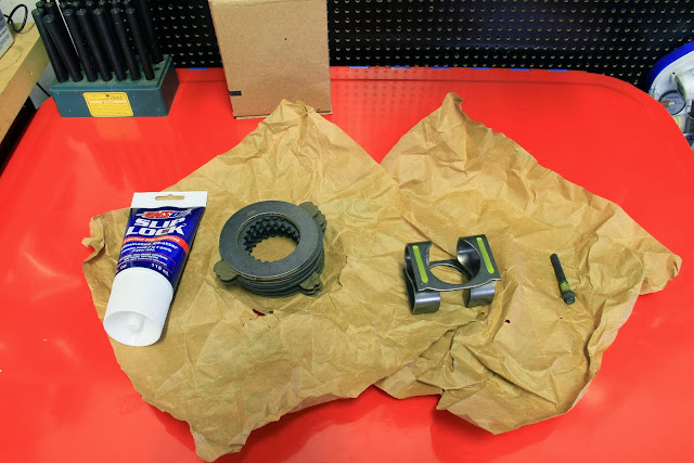
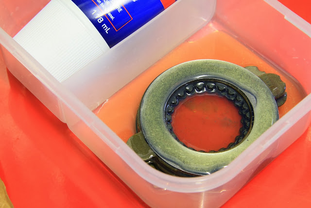
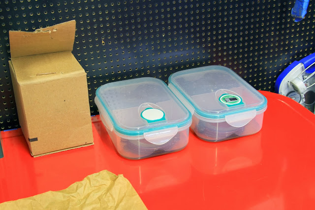
Before you even begin removing the wheels, first and for most remove the contents of your new Traction-Lok clutch pack from the box, ensure everything is accounted for(shims, clutches, new s-spring and pinion shaft lock bolt) be mindful to keep the shims and clutches in their respective order (they come properly stacked from the factory). These clutches need to soak in friction modifier for a minimum of 15 minutes, realistically the longer the better. I let mine sit overnight in AMSOIL Slip Lock additive. To Keep dust off of them cover them up.
With the transmission in neutral, the Jeep raised and secured. Remove the rear wheels.
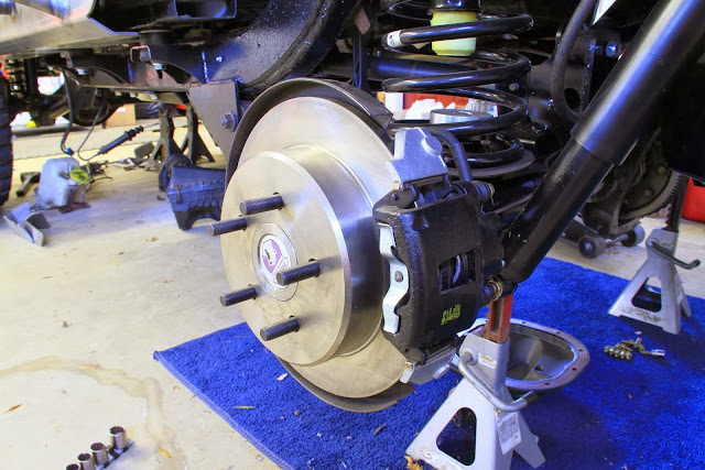
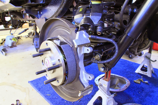
Remove the brake drums or rotors, calipers and brake sensors.
Remove the cover and drain the lubricant. Discard the drained lubricant.
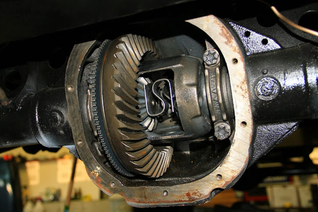
Remove the rear axle shafts. In most cases the Ford 8.8, came with c-clip’s, which are removed by pushing in slightly on the axle shaft toward the center houseing. In my case I have changed out the rear axles shafts to eliminate the c-clip’s with the Yukon Ultimate 88 axle kit.
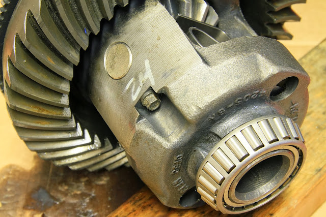
Mark the bearing caps, bearing shims and bearing (side for side) to facilitate re-assembly and to ensure that they go back in their respective locations.
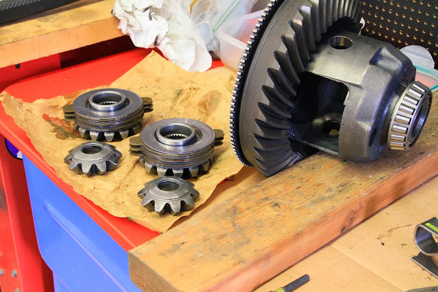
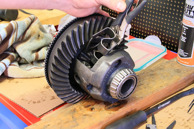
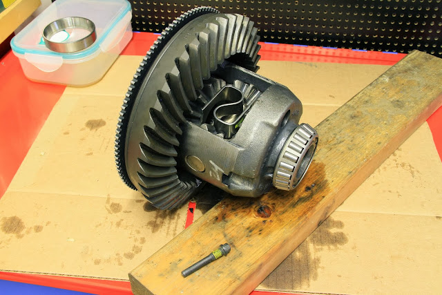
Remove the carrier from the differential housing and disassemble. Using some AMSOIL heavy duty degreaser I fully cleaned the spider gears and inspected them for any damage.
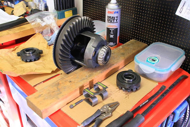
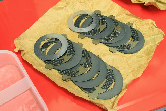
Here is the difference between the two clutch plates, new carbon fiber clutches on left, old standard clutch on the right.

Next is stacking the clutches and shims on the spider gears, the stacking order is as follows. Spider Gear-Shim-Clutch-Shim-Shim-Clutch-Shim-Clutch-Steel
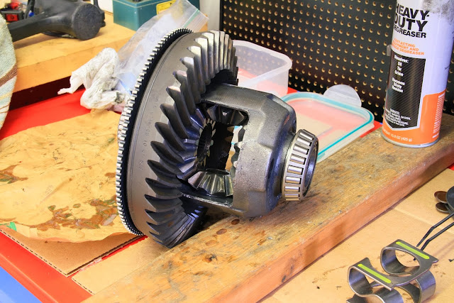
Install the clutch packed spider gears first, start with the gear on the same side as the carrier ring gear, then the opposite side, next turn the top and bottom spider gears with the trust washers into place making sure they are installed evenly because the cross shaft needs to go thought them.
This is the difficult part, installing your new s-spring. Place the spring in a vice and clamp it down until the metal touches itself as pictured here with a small pair of needle nose vice grips.

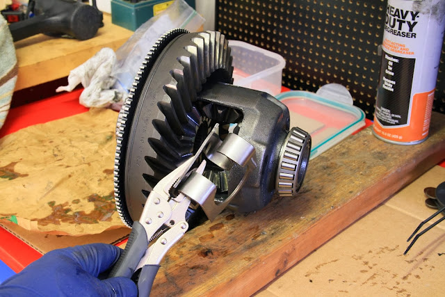
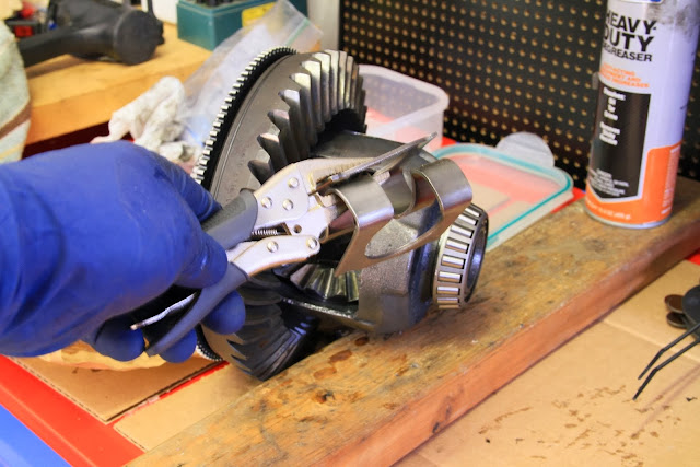
Place the spring in this position and give it a good wrap with a brass or dead blow hammer until it pops into the housing, then tap it down until it is in the correct position.
If you are looking for a video demonstration of the S-Spring install check this out, this is Ken from BadShoeProductions
(I was able to do the next step on the bench because of my non c-clip axles, if you have c-clip axles you will need to install the carrier first back into the differential, install the axle shafts and c-clip’s and then place the cross pin and lock bolt in place. Either way, make sure you check that everything is lined up before installing the carrier into the housing)
Next install the cross shaft (making sure the hole for the lock bolt is on the correct side and lined up) and cross shaft lock bolt. Tighten to (20-41 N*m) 15-30lb/ft.
Now simply reverse order for installation.
When installing the carrier, the side shims and bearings can be a little tricky to hold all together. If you can get a helper for this part it will make things much easier. If you don’t have a helper, try using some white lithium grease to help hold all the pieces in place.
Tighten the bearing caps back down.
Install the axle shafts. Install the cover with either silicone gasket sealant or lube locker gasket. Install the brake components. Install tires. Torque everything to spec.
I then filled up the differential with 5.7 Pints (2.85 Quarts) of AMSOIL Severe Gear® 75W-140 and 4 oz. of AMSOIL Slip Lock.
Hopefully all of this helps someone who is thinking of doing this.
So here is a little write-up.
Before you even begin removing the wheels, first and for most remove the contents of your new Traction-Lok clutch pack from the box, ensure everything is accounted for(shims, clutches, new s-spring and pinion shaft lock bolt) be mindful to keep the shims and clutches in their respective order (they come properly stacked from the factory). These clutches need to soak in friction modifier for a minimum of 15 minutes, realistically the longer the better. I let mine sit overnight in AMSOIL Slip Lock additive. To Keep dust off of them cover them up.
With the transmission in neutral, the Jeep raised and secured. Remove the rear wheels.
Remove the brake drums or rotors, calipers and brake sensors.
Remove the cover and drain the lubricant. Discard the drained lubricant.
Remove the rear axle shafts. In most cases the Ford 8.8, came with c-clip’s, which are removed by pushing in slightly on the axle shaft toward the center houseing. In my case I have changed out the rear axles shafts to eliminate the c-clip’s with the Yukon Ultimate 88 axle kit.
Mark the bearing caps, bearing shims and bearing (side for side) to facilitate re-assembly and to ensure that they go back in their respective locations.
Remove the carrier from the differential housing and disassemble. Using some AMSOIL heavy duty degreaser I fully cleaned the spider gears and inspected them for any damage.
Here is the difference between the two clutch plates, new carbon fiber clutches on left, old standard clutch on the right.
Next is stacking the clutches and shims on the spider gears, the stacking order is as follows. Spider Gear-Shim-Clutch-Shim-Shim-Clutch-Shim-Clutch-Steel
Install the clutch packed spider gears first, start with the gear on the same side as the carrier ring gear, then the opposite side, next turn the top and bottom spider gears with the trust washers into place making sure they are installed evenly because the cross shaft needs to go thought them.
This is the difficult part, installing your new s-spring. Place the spring in a vice and clamp it down until the metal touches itself as pictured here with a small pair of needle nose vice grips.
Place the spring in this position and give it a good wrap with a brass or dead blow hammer until it pops into the housing, then tap it down until it is in the correct position.
If you are looking for a video demonstration of the S-Spring install check this out, this is Ken from BadShoeProductions
(I was able to do the next step on the bench because of my non c-clip axles, if you have c-clip axles you will need to install the carrier first back into the differential, install the axle shafts and c-clip’s and then place the cross pin and lock bolt in place. Either way, make sure you check that everything is lined up before installing the carrier into the housing)
Next install the cross shaft (making sure the hole for the lock bolt is on the correct side and lined up) and cross shaft lock bolt. Tighten to (20-41 N*m) 15-30lb/ft.
Now simply reverse order for installation.
When installing the carrier, the side shims and bearings can be a little tricky to hold all together. If you can get a helper for this part it will make things much easier. If you don’t have a helper, try using some white lithium grease to help hold all the pieces in place.
Tighten the bearing caps back down.
Install the axle shafts. Install the cover with either silicone gasket sealant or lube locker gasket. Install the brake components. Install tires. Torque everything to spec.
I then filled up the differential with 5.7 Pints (2.85 Quarts) of AMSOIL Severe Gear® 75W-140 and 4 oz. of AMSOIL Slip Lock.
Hopefully all of this helps someone who is thinking of doing this.
Last edited:
IceKnight
New member
I then moved onto my new custom sound bar that I have been working on to replace my sound bar that housed two 6.5 JL Audio subs and two Pioneer 6.5’s. This new build will be housing a set of Polk 6.5’s and a Pioneer 8 inch subwoofer.
This is what I plan on running for audio equipment
Head Unit: Alpine CDE-HD149BT
Amp: Alpine PDX-5
Front Speakers: Polk Audio MM521
Rear Speakers: Polk Audio MM651
Subwoofer: Pioneer TS-SW841D
To start this build off, I needed to strip the sound bar down, which was quite easy this time because apparently the glue guy at the factory was being a bit stingy, I’m not complaining, it made my life easier. Obviously I removed the speakers, lights and then pulled the outer cover off along with thick and thin foam off.


Next was to remove the section of metal where I would be building the frame of the sub enclosure. I choose to put the sub on the driver’s side, so passengers in the back would not hit their heads getting in and out. I only needed three cuts because one side was only held in by a slotted/bent tab arrangement.


Next I cut three pieces of mdf to build out the walls of the enclosure. I did these a little over sized and slowly sanded them down for a nice sung fit.

Next I moved on to the base of the enclosure, I started with paper and then transferred it to Masonite and curved the sharp edge to the angle I wanted.


Happy with the fitment of the three sides I glued them in place with two part glue. If you notice I positioned the wood only half way under the metal. I did this so I would have something to staple the fabric for the top of the enclosure to. I also prepped the painted area so the adhesive would bite in for a nice strong hold for the base of the enclosure. You’ll see four holes drilled in it as well. I did that so I could bolt the base in while the glue set up.

Next I built the frame to hold the sub and test fit it for clearances. Everything looked good so I glued it all in place. You can see in the second picture that the four holes that I had drilled for holding the base in place have been filled in. By this time the glue had dried up and was more than strong enough to hold the structure. You will also notice that on the right side of the sound bar, along the metal, I drilled many small holes. These holes will act as anchor points for the fabric to be glued to allowing me to create the shape of the enclosure. The speaker ring has also had a slight change; that being the small lip I routed into it so I had a place staple the fabric down leaving a nice smooth finished edge in the end for the speaker to mount to.


Here is the fabric all stapled/glued down and ready for fiberglass resin. I keep saying fabric, what this is, is unbacked speaker box carpet. It stretches in every direction and after it is soaked with resin you end up with an extremely rigid shell.

I popped it onto the roll bar real quick to see how it would look. It will be a nice clean fit, sort of hiding in plain sight.


Mixed up the fiberglass resin and soaked the fabric, let things cure up and then sanded it down.


I then added some Rage Gold body filler and sanded it down again, slapped on a quick layer of paint and that is where is sits now.


I have wrapped the sound bar just this weekend and just need to get my speakers and install everything.
This is what I plan on running for audio equipment
Head Unit: Alpine CDE-HD149BT
Amp: Alpine PDX-5
Front Speakers: Polk Audio MM521
Rear Speakers: Polk Audio MM651
Subwoofer: Pioneer TS-SW841D
To start this build off, I needed to strip the sound bar down, which was quite easy this time because apparently the glue guy at the factory was being a bit stingy, I’m not complaining, it made my life easier. Obviously I removed the speakers, lights and then pulled the outer cover off along with thick and thin foam off.
Next was to remove the section of metal where I would be building the frame of the sub enclosure. I choose to put the sub on the driver’s side, so passengers in the back would not hit their heads getting in and out. I only needed three cuts because one side was only held in by a slotted/bent tab arrangement.
Next I cut three pieces of mdf to build out the walls of the enclosure. I did these a little over sized and slowly sanded them down for a nice sung fit.
Next I moved on to the base of the enclosure, I started with paper and then transferred it to Masonite and curved the sharp edge to the angle I wanted.
Happy with the fitment of the three sides I glued them in place with two part glue. If you notice I positioned the wood only half way under the metal. I did this so I would have something to staple the fabric for the top of the enclosure to. I also prepped the painted area so the adhesive would bite in for a nice strong hold for the base of the enclosure. You’ll see four holes drilled in it as well. I did that so I could bolt the base in while the glue set up.
Next I built the frame to hold the sub and test fit it for clearances. Everything looked good so I glued it all in place. You can see in the second picture that the four holes that I had drilled for holding the base in place have been filled in. By this time the glue had dried up and was more than strong enough to hold the structure. You will also notice that on the right side of the sound bar, along the metal, I drilled many small holes. These holes will act as anchor points for the fabric to be glued to allowing me to create the shape of the enclosure. The speaker ring has also had a slight change; that being the small lip I routed into it so I had a place staple the fabric down leaving a nice smooth finished edge in the end for the speaker to mount to.
Here is the fabric all stapled/glued down and ready for fiberglass resin. I keep saying fabric, what this is, is unbacked speaker box carpet. It stretches in every direction and after it is soaked with resin you end up with an extremely rigid shell.
I popped it onto the roll bar real quick to see how it would look. It will be a nice clean fit, sort of hiding in plain sight.
Mixed up the fiberglass resin and soaked the fabric, let things cure up and then sanded it down.
I then added some Rage Gold body filler and sanded it down again, slapped on a quick layer of paint and that is where is sits now.
I have wrapped the sound bar just this weekend and just need to get my speakers and install everything.
sean.m.adams33
New member
This is one hell of a build. Awesome skills man. Keep it up!
IceKnight
New member
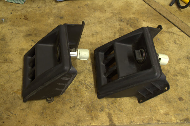
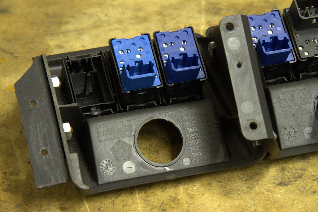
So to move this along more, here is how I mounted two OEM panels next to each other on the dash and got switches that match as close as possible to factory.
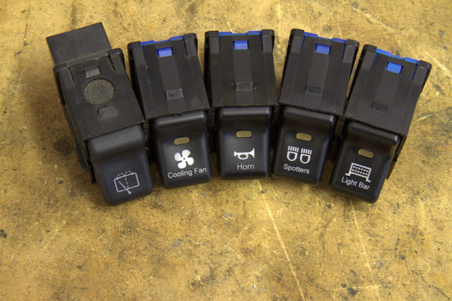
Here are the switches I picked up, rear wiper is factory, then I picked up cooling fan for my FAL radiator fan, horn because my steering wheels horn button does not work, spot lights and a light bar.
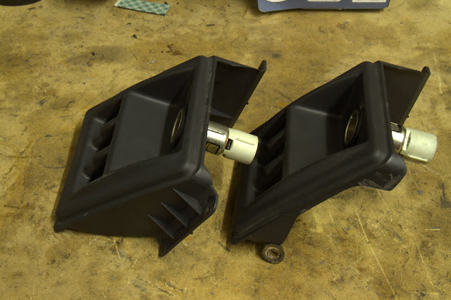
Here are the two panels I was working with.
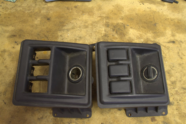
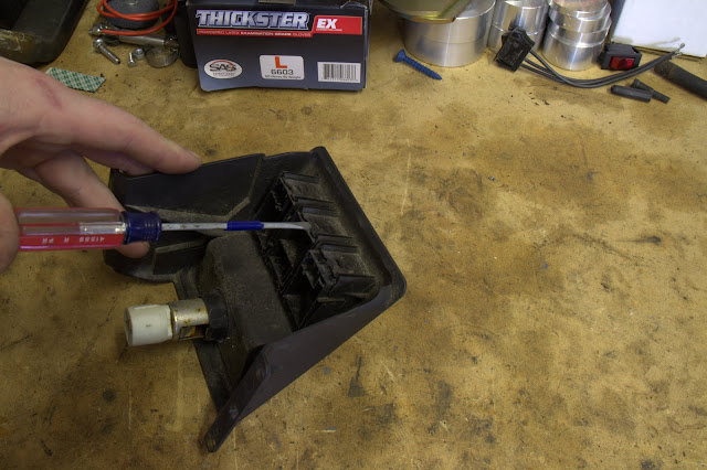
And removing the last three blanks from the second panel.
Dash panel before I started cutting and then after.

(Sorry about the crappy picture)

My first trimming of the switch panel, removed the mounting holes and support ribs of the second (passenger side) panel.
Next I created a cut out template of the shape I needed to replicate for the panels to mount flush against one other.

I then transferred the outline of the template onto the passenger side switch panel.
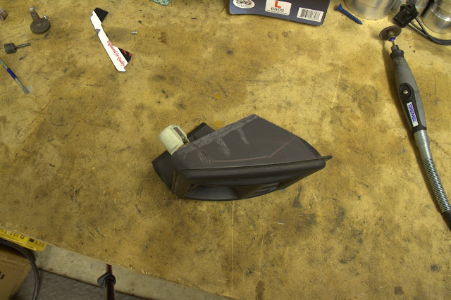
Next I used my dremel with a plastic cut off wheel to trim the outline.
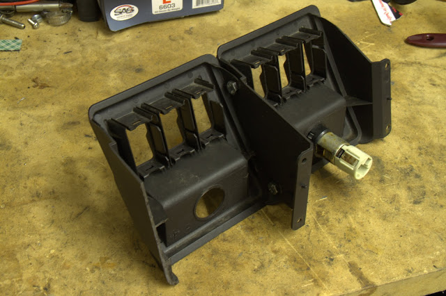
After a bunch of sanding down of the edges to make the fitment just right, I bolted the two switch panels together. You’ll also notice that on the left hand side of the picture the panel has been cut off already. I did this before bolting them together. I placed both of the panels, switch side down but in opposite position of how they will be mounting in the Jeep and holding them flat on the bench I traced the mounting height of the side panel, on to the panel I needed to cut to match the correct height for the passenger side mounting location.
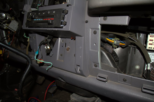
Here I marked out on the dash where I would be drilling the mounting holes.
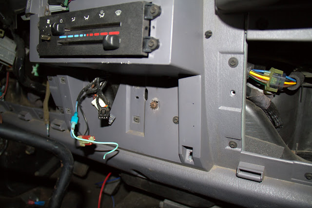
First holes drilled in the dash and then I place the screw retainers in the holes.
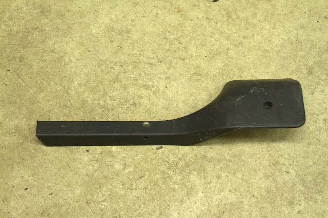
I test fit the switch panel and it fit like a glove. I attached it with a piece of l-shaped plastic I had laying around. Some of you may recognize the piece it came from.

And here is the finished installation…still need to finish up the actual wiring part of things but Ill be working on that tomorrow.
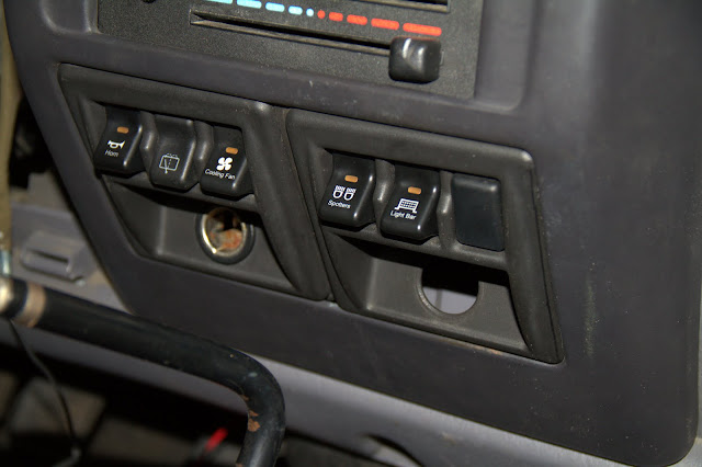
Here are the switches I picked up, rear wiper is factory, then I picked up cooling fan for my FAL radiator fan, horn because my steering wheels horn button does not work, spot lights and a light bar.
Here are the two panels I was working with.
And removing the last three blanks from the second panel.
Dash panel before I started cutting and then after.
(Sorry about the crappy picture)
My first trimming of the switch panel, removed the mounting holes and support ribs of the second (passenger side) panel.
Next I created a cut out template of the shape I needed to replicate for the panels to mount flush against one other.
I then transferred the outline of the template onto the passenger side switch panel.
Next I used my dremel with a plastic cut off wheel to trim the outline.
After a bunch of sanding down of the edges to make the fitment just right, I bolted the two switch panels together. You’ll also notice that on the left hand side of the picture the panel has been cut off already. I did this before bolting them together. I placed both of the panels, switch side down but in opposite position of how they will be mounting in the Jeep and holding them flat on the bench I traced the mounting height of the side panel, on to the panel I needed to cut to match the correct height for the passenger side mounting location.
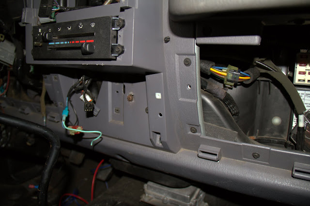
Here I marked out on the dash where I would be drilling the mounting holes.
First holes drilled in the dash and then I place the screw retainers in the holes.
I test fit the switch panel and it fit like a glove. I attached it with a piece of l-shaped plastic I had laying around. Some of you may recognize the piece it came from.
And here is the finished installation…still need to finish up the actual wiring part of things but Ill be working on that tomorrow.
darkknight1999
Member
Every time I read through your thread is still amazes me
Great Job bro! (Except he's actually my brother) :rock:
Great Job bro! (Except he's actually my brother) :rock:
IceKnight
New member
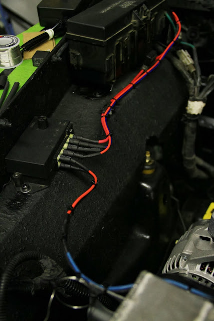
After the switches got all wired up and working.
I moved onto the next part of the build, engine start. I checked rechecked and checked again everything for motor start. This included taking all the valve springs out to remove the centers for cam shaft break in.
Then started filling everything with fluid.

Things took a little fiddling with the timing but after that things fired up boy did things get hot.
This was the first start/break-in run. After this run, I dumped the oil, changed the valve springs again back to dual topped things off with fresh change of Amsoil break-in oil and a new filter. Then I ran it again for another 20 minutes. This time the cat was glowing just like the header on first start and it was spitting flames lol After the second run I again drained the oil and replaced it and the filter with fresh Amsoil break-in oil.
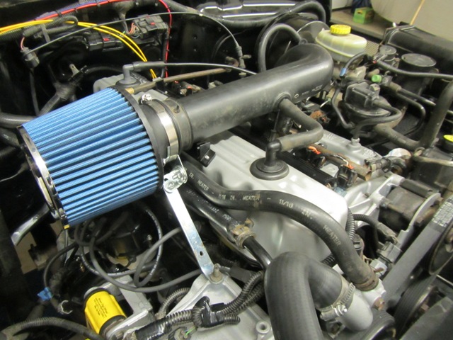
Just after this I got my intake all set up. It consists of part of a factory intake (which I used on motor break-in), Ea Air Filter and pre-filter along with a custom made little filter holders I made up to hold it all tight.

I moved onto the next part of the build, engine start. I checked rechecked and checked again everything for motor start. This included taking all the valve springs out to remove the centers for cam shaft break in.
Then started filling everything with fluid.
Things took a little fiddling with the timing but after that things fired up boy did things get hot.
This was the first start/break-in run. After this run, I dumped the oil, changed the valve springs again back to dual topped things off with fresh change of Amsoil break-in oil and a new filter. Then I ran it again for another 20 minutes. This time the cat was glowing just like the header on first start and it was spitting flames lol After the second run I again drained the oil and replaced it and the filter with fresh Amsoil break-in oil.
Just after this I got my intake all set up. It consists of part of a factory intake (which I used on motor break-in), Ea Air Filter and pre-filter along with a custom made little filter holders I made up to hold it all tight.